International Plastic Laboratories and Services
Georgetown, Texas 78633
Georgetown, Texas 78633

Clamp Tonnage - Determining the right amount of clamp tonnage required
Sizing The Clamp Unit
The Clamp Unit of an injection molding machine is rated by the maximum amount of clamp force that the machine is capable of producing. This force is required in order to keep the mold closed during the injection process, which is the primary purpose of the clamp unit. Normally, the force rating is stated in tons. So, a specific machine having a rating of 200 tons is capable of producing a maximum clamping force equivalent to a total of 200 tons. But, how much clamp force is necessary?
How Much Force Is Required?
The answer to this question depends on how much injection pressure is required to inject a specific plastic material into a mold. This is determined by the viscosity (the thickness value) of the material. Viscosity is a value that must be correctly understood, and an explanation follows.
Thicker materials require greater injection pressures and are difficult to flow. There are flow ranges in which each material will fall, and these can be classified as "high flow", "average flow", and "low flow". The Melt Flow Index test determines the flow rate of any plastic, and the material suppliers make this information readily available on their material information sheets. These index numbers may range, for instance, from 5 to 20. The lower numbers signify that the specific material does not flow easily so would be classified as low flow. The higher numbers signify a material that flows very easily so would be classified as high flow.
It is not as important to remember a specific flow number as it is to know in what range a material falls; high flow, average flow, or low flow. Then, understanding that it requires more injection pressure to inject a low flow material than a high flow material, it is understood that a low flow material will require much more clamp force to keep the mold closed against that higher injection pressure.
A comparison of two materials will show the difference. A product molded of polycarbonate (a low flow plastic) may require an injection pressure of 15,000 psi, while that same product molded of acetal (a high flow plastic) may require only 5,000 psi. Therefore, the polycarbonate product will require a clamp force on the mold that is approximately three times (3) that for the acetal product.
Determining Projected Area
The method used for determining the required clamp force is to take the projected area of the part to be molded and multiply that number by a factor of from 2 to 8. Projected area is calculated by multiplying length times width. The sketch that follows is an example.
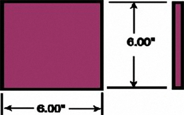
The projected area of this part is found by multiplying the length dimension (6.00") times the width dimension (also 6.00"). The depth dimension ( no dimension) is only important if it is more than 1 inch. This will be explained later.
So, for this particular product, the projected area is determined by multiplying 6" times 6". The result is an area of 36 square inches.
Clamp force requirements can now be calculated by multiplying the 36 square inches by a factor of between 2 and 8 tons per square inch. The lower numbers can be used for high flow materials and the higher numbers can be used for low flow (stiff) materials.
For this example, polycarbonate has been selected as the material for molding. Polycarbonate is fairly stiff and a lower flow material, so the clamp factor used must be towards the high side. Experience has shown that a clamp factor of 5 tons per square inch is adequate for polycarbonate. That means that the 36 square inch projected area found above must be multiplied by the clamp factor of 5 tons per square inch, to result in a total clamp tonnage requirement of 180 tons (36 x 5 = 180). There should be a safety factor of 10% added, so the final clamp force needed is 198 tons. The machine with the closest rating for this product would be a 200 ton machine.
It must be noted that these numbers are only correct if there is a shutoff land surrounding the part. If that land does not exist the clamp tonnage will have to be doubled or tripled, or more! This may result in mold damage, machine damage, and longer cycle times. (See our Glossary for the definition of a shutoff land.)
Summarizing, the total clamp force required for a specific product is determined by finding the projected area of that product,
[Projected area = length x width]
and multiplying that area by a clamp factor of between 2 and 8. If in doubt, use 5.
[Projected area x 5 = clamp force required]
What about that "D" dimension?
The "D" dimension only becomes important if the plastic part is more than 1 inch deep. That is not the thickness of the wall, but the total depth of the part. For every inch of depth over 1 inch the total clamp force must be increased by 10%. So, if the part shown above was 2 inches deep the clamp force would be increased by 18 tons (10% increase for every inch over 1") to a total of 198. Add 10% for safety factor and the required force increases to 217.8 tons. The nearest machine size to that requirement would probably be a 225 ton machine.
END